In practice, the most common single-storey full-frame industrial buildings are 3...20 thousand square meters. They can be crane-less or equipped with overhead electric cranes.
The spans of the buildings are 12, 18, 24 and 30 m, columns are 6 and 12 m high, buildings are 8.4 to 18 m high. The weight of prefabricated elements varies from 2.5 to 33 t.
The buildings are characterized by uniform cells, structures and large dimensions in longitudinal and transverse directions. The main advantages of single-storey industrial buildings are their relative cheapness, the possibility of using a sparse grid of columns and the transfer of loads from technological equipment directly to the ground. Such buildings usually have a rectangular outline in plan, without height differences, with spans in one direction.
Universal space-planning and constructive solutions of the buildings, which allow applying industrial methods of installation, have been developed. A limited number of combinations of building parameters or dimensional schemes is established. The size of the spans are associated with a certain height and pitch of the columns, over the crane dimensions. All elements of the frame, fence and cover of single-storey buildings are multiples of the nominal dimensions of the enlarged modules: planning - 6 m, height - 1.2 m.
Sequence of work
One-storey industrial buildings are usually assembled from standard elements, serially produced at precast concrete plants. Prefabricated structures of single-storey buildings are divided into load-bearing and enclosing. The load-bearing ones include precast foundations, columns, crane beams, trusses and trusses, the enclosing ones are covering slabs, rond-beams (strapping beams) and wall panels.
When the spans of buildings are 30 m and more, steel trusses are used, buildings with smaller spans can be covered by reinforced concrete trusses with parallel belts or with the upper curvilinear belt - arched or segmental. It should be noted that the erection of buildings with reinforced concrete frame is more labor-intensive compared to a similar building in metal structures.
Buildings of precast reinforced concrete elements are assembled element by element, they are not grouped into spatial blocks of the complexity of joints, the weight of reinforced concrete block exceeds the weight of a similar block of metal structures in 3 ... 5 times.
The mounting of structures is considerably complicated due to the presence of "wet processes" - the necessity of joints caulking.
Further installation of structures after the installation of columns in the foundations of the steel vault type and their monolithing can be started only after the concrete strength of the monolithing joint reaches 70% of its natural strength. In this regard, additional difficulties arise when carrying out works in winter conditions.
If there are several cranes at a construction site, the frame can be erected in several parallel and consecutive flows: prefabricated foundations, columns, connections between columns, crane beams and coating elements, wall panels. Such organization of works allows to significantly reduce the installation time.
After digging pits or trenches for foundations, leveling and compacting the foundations, the installation of foundations can begin. With a large-depth foundations or a solid excavation for the building, the crane will move along the bottom of the excavation.
Columns are installed in the second flow and only after the completion and acceptance of the completed zero cycle work on the first excavation. Such works include: acceptance of installed foundations for column installation, backfilling of trench slots and pits, grading of soil within the excavation, laying of roads for transport, preparation of sites for structural storage and crane operation. The optimal solution after the leveling is done is to make a concrete floor preparation over the entire area of the trench.
It is allowed to make a hard surface of reinforced concrete road slabs for the movement of transport and cranes. In this case, sandy preparation is recommended for the storage areas of structures.
Columns up to 12 m in height usually are not dared, their stability is provided only by embedding in the foundation. When installing higher columns, they must be ducked in the plane of least rigidity (along the row of columns). After the required strength of the joints between the columns and the foundations is achieved, you can start assembling the ties and laying the crane girders. After the fastening details of the crane beams are tacked to the column cantilevers and the joints are sealed, the braces between the columns are removed.
Mounting of the crane girders is usually performed in the same flow with the coating elements of the building. Each cell of the building frame should be mounted in an integrated manner: install all the crane beams, trusses, trusses (one or two), and on them all the floor slabs per cell. The plates are mounted sequentially from one end to another, the first plate for the outermost span is installed from the hinged platforms fixed to the columns of the first row, the plate for the middle span - from the previously installed plates of the outermost span.
The wall panels are installed in the final assembly flow, usually by an independent crane. The panels are hung at once for the entire height between the adjacent columns, usually in conjunction with the process of installing the window profiles and caulking between the elements. When erecting single-storey industrial buildings, there are no prefabricated warehouses. Structures are delivered to the installation area in the third shift, unloaded and arranged at the lifting points. Stock of structures shall be not less than for two days of work, at interruptions in supply the stock must increase. Structures can also be delivered during the daytime, in this case the structures are lifted towards the mounting direction.
Organization of erection of buildings.
To reduce the construction time, the building is usually assembled from the ends to the middle, from the middle to the ends, another direction is also possible, it is important that each temperature unit is assembled independently. There are two independent object work streams, each of which can include several specialized streams for the installation of individual structures - columns, crane beams, coating elements and wall panels. Each specialized flow provides the mounting crane and the corresponding set of mounting devices.
If the building under construction has a large area, it is divided into several grips. The sizes of the segments are taken depending on the space-planning and design solutions of the building, the peculiarities of its commissioning, the labor intensity of the work. Partitioning of the building into sections or assembly sections facilitates streamlined production, the emergence of each site of an independent installation flow. The works in the areas can be performed sequentially by one flow or in parallel and simultaneously by several specialized flows in several areas.
Methods of combining construction cycles
Depending on the possible and expedient degree of combination of construction work, assembly of structures and technological equipment, industrial buildings are erected using open, closed, combined or combined methods (Fig. 1). These methods reflect different degrees of combination and sequence of works, which must always be taken into account when organizing the installation of building structures and the erection of buildings.
The main cycles of construction of one-story industrial buildings include the erection of underground and aboveground parts of the building, which includes: excavation of pits and trenches for the building foundations and technological equipment, installation of building foundations and concreting foundations for equipment, installation of aboveground structures and erection of built-in floors, installation of technological equipment and piping, finishing works.
The open method consists in the fact that initially performs all work on the construction of the underground part of the job site, and then mounts structures of the above-ground part of the building, technological equipment, pipelines, performs all finishing work. The underground cycle includes all works on the construction of underground structures - foundations for the building and equipment, basement floors with ceilings over them, laying and backfilling of all communications, construction of flooring in a building without basements.
After completion of the underground cycle of work, including preparation for floors, the remainder of the site shall be graded.
The performance of all underground cycle works in the first instance to enable the most efficient installation of the above-ground part of the building or structure is one of the most important conditions for successful construction by industrial methods. However, depending on the space planning and technological solutions of buildings and construction conditions, other methods may be more effective.
Fig. 1. Methods for combining construction cycles: IV - open: 1 - erection of the underground part; 2 - erection of the frame; 3 - installation of process equipment; 4 - finishing works; II -
closed: 1 - underground part under the frame; 2 - building frame; 3 - underground part of technological equipment and communications; 4 - installation of technological equipment; 5 - finishing works; III - combined: 1 - excavation of a common foundation pit of the building; 2 - concreting of bases for equipment; 3 - installation of the building frame; 4 - installation of technological equipment; 5 - finishing works
- finishing works; IV - combined
- Work performance using open-pit (I) and closed-pit (II) methods
closed (II) method
With the closed method, at each installation site, excavations and foundations are first performed only for the building, after which the frame of the building is assembled. When the installation work inside the building frame is completed, excavations are excavated, foundations are built for the built-in structures (storeys) and for the process equipment and all underground facilities. Only after that, the storey structures, process equipment, pipelines are installed and all finishing works are performed.
Closed method can be more rational in the case where the foundations for the equipment occupy a large part of the building and the need to build a developed network of underground facilities. This complicates the movement of cranes, requires additional costs for the device of passageways. Closed method allows you to disperse the work to apply self-propelled cranes, with greater maneuverability and lower operating costs than the tower used for installation of an open method. Most of the work is performed after the construction of the cover of the building, which is important for protection against precipitation.
With the combined method, first the common excavation for the underground facilities, foundations for the equipment and the building are excavated. Concreting of foundations for equipment and other underground works is combined with the installation of the building frame so that by the time the foundations for equipment are delivered, the frame installation is completed at other work sites and it is possible to proceed to the installation of process equipment.
With the combined method of the spans with a large saturation of the process equipment and developed underground facilities erected by closed method, and the spans with poorly developed underground facilities and a small amount of process equipment - open. In this method the installation cranes are located in the spans with poorly developed underground facilities.
Installation of precast reinforced concrete columns.
A column is an architecturally finished vertical support, usually circular or rectangular in cross-section, supporting a beam, girder slab or the heel of an arch [10].
When columns arrive at the construction site, the following operations must be performed:
- checking the availability of the accompanying document on the quality of products and their compliance with the specified type (grade) - GOST 18979-90.
- checking for the presence of a mark and the QCD stamp on the products in accordance with GOST 13015-2003 and their compliance with the data specified in the accompanying document;
- preliminary visual inspection of the products to detect inadmissible defects and damages (cracks, chips, concrete overlaps) and the presence of reinforcing bars for the joints with the beams and columns.
After the columns have been unloaded, the sampling instrumental measurements are taken to determine the geometric parameters of the columns (GOST 26433.0-85 and GOST 26433.1-89), the correctness of the placement
the quality of the surfaces, the presence of cracks with the opening of more than 0.1 mm, the strength of the concrete.
When controlling the concrete strength of the columns should be guided by GOST R 53231-2008.
Deviations from the design position of the mounted columns shall not exceed the limit values:
- from the alignment of landmarks (geometric axis marks) in the lower section of the columns with the mounting landmarks (break axis risks) - 8 mm;
- alignment of landmarks (geometric axis marks) in the upper section of the columns with the breakdown axis marks when the length of the columns , m:
- up to 4 - ±12 mm;
- from 4 to 8 - ±15 mm;
- from 8 to 16 - ±20 mm.
The main requirements for slinging devices for columns mounting is the need for automatic or remote unslinging of columns from the mounting horizon and ensuring vertical position of the column when lifting.
If there are special slinging holes in the column, unified traverses with a finger gripper and a pin lock with a device for remote slinging are used.
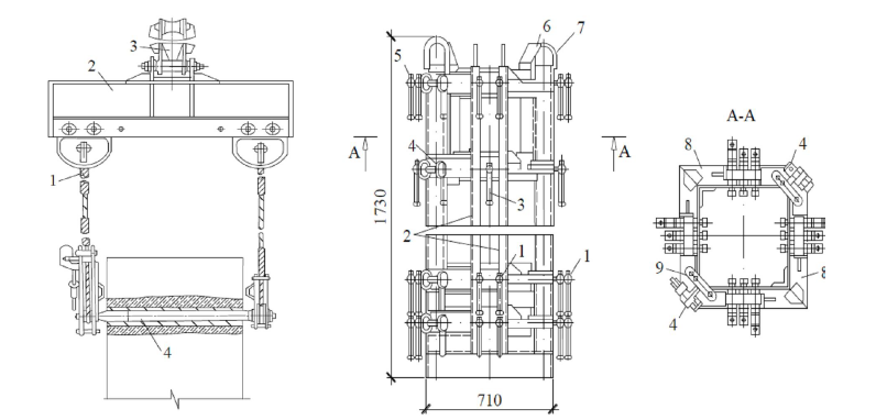
| Fig. 2. Unified Traverse beam for mounting the con- bones: 1 - sling; 2 - beam; 1 - sling; 2 - beam; 3 - hanger; 4 - pin |
Fig. 3. Single detachable conductor with with coupling screws of "Mosorgstroy" design "Mosorgstroy: 1 - screws for fastening 1 - screws for fastening the conductor to the head of the column; 2 - columns of the conductor foot; 2 - uprights of the conductor; 3 - screws for alignment of the column bottom screws; 3 - column bottom leveling screws; 4 - binding screws; 5 - screws for column top leveling; 6 - screws for column top leveling. top of the column; 6 - guide rails; 7 - hinges for mounting; 8 - vertical column Hinges for assembling; 8 - Conductor sections; 9 - Latch latch |
The device for temporary fastening and alignment of columns is a single detachable conductor with tightening screws (Fig. 3) consisting of two L-shaped half-frames connected diagonally by four pairs of tightening screws and a latch. There are four rows of screws on each side of the conductor, of which the lower two pairs serve to secure it to the head of the lower column and the upper two pairs serve to align and temporarily secure the column being installed.
Assembling precast reinforced concrete trusses
Truss truss is a building load-bearing structure for covering, as a rule, large spans, is a flat structure of rod elements connected in hinged and / or rigid nodes, consisting of elements of the upper compressed chord, the lower stretched chord and struts, struts, bracing that unite the chords in a single structure [11].
Trusses are divided into types (Fig. 4):
- strut segmental for roofs with pitched roofs;
- Without sloping segmental for the roofs with a pitched roof;
- the same for roofs with a low slope roof;
- triangular sillless for pitched roofs.

Split segment truss

Slantless segmental truss

Segmental frameless roof truss for low-slope roofs

A sill-less triangular truss
Figure 4. Types of trusses
When rafters arrive at the construction site, the following operations must be performed:
- check the availability of the accompanying document on the quality of products and their compliance with the specified type (grade) - GOST 20213-89;
- checking the availability of the marking and the quality control stamp on the products in accordance with GOST 13015-2003 and their compliance with the data specified in the accompanying document;
- preliminary visual inspection of the products to find out if they have no inadmissible defects and damages (cracks, concrete damages in the area of tension armature anchorage, chipping, concrete overlaps).
The installation of trusses is usually performed in the same flow with the floor slabs using self-propelled jib cranes with crane booms or tower cranes (in the construction of multistoried buildings).
In the construction of single-storey buildings with a column spacing of 12 m, the installation of trusses and roof slabs can be carried out in parallel by separate (differentiated) flows using two mobile cranes. In this case, the crane installing the roof slabs moves in transverse passages. The use of this method requires a special layout of the elements, a strict coordination of parallel streams and the observance of special measures of safe conduct of work. The deviations from the designed position of the assembled trusses must not exceed the limit deviations:
- from the alignment of landmarks (marks of geometric axes, edges) in
the bottom cross-section of the installed elements with the set guidelines
- 8 mm;
- from the alignment of reference points (marks of geometrical axes, faces) in
in the upper cross-section of the installed elements with reference marks
If the height of the element on the support, m
- up to 1 - 6 mm;
- from 1 to 1.6 - 8 mm;
- symmetricity (half of the difference in the depth of support of the
Symmetry (half of the difference in the depth of resting of the element ends) in the direction of the span to be bridged, at element length, m
- from 4 to 8 - 6 mm;
- from 8 to 16 - 8 mm;
- above 16 - 10 mm.
- in the distance between the axes of top chords of trusses in the middle of the span
- 60 mm.
For lifting trusses the devices are used (Fig. 5):
- slinging devices;
- semi-automatic gripper;
- Universal traverse used for installation of trusses PK-01-129/78 and 1.463-3 series, length 18 m and weight up to 12 t.
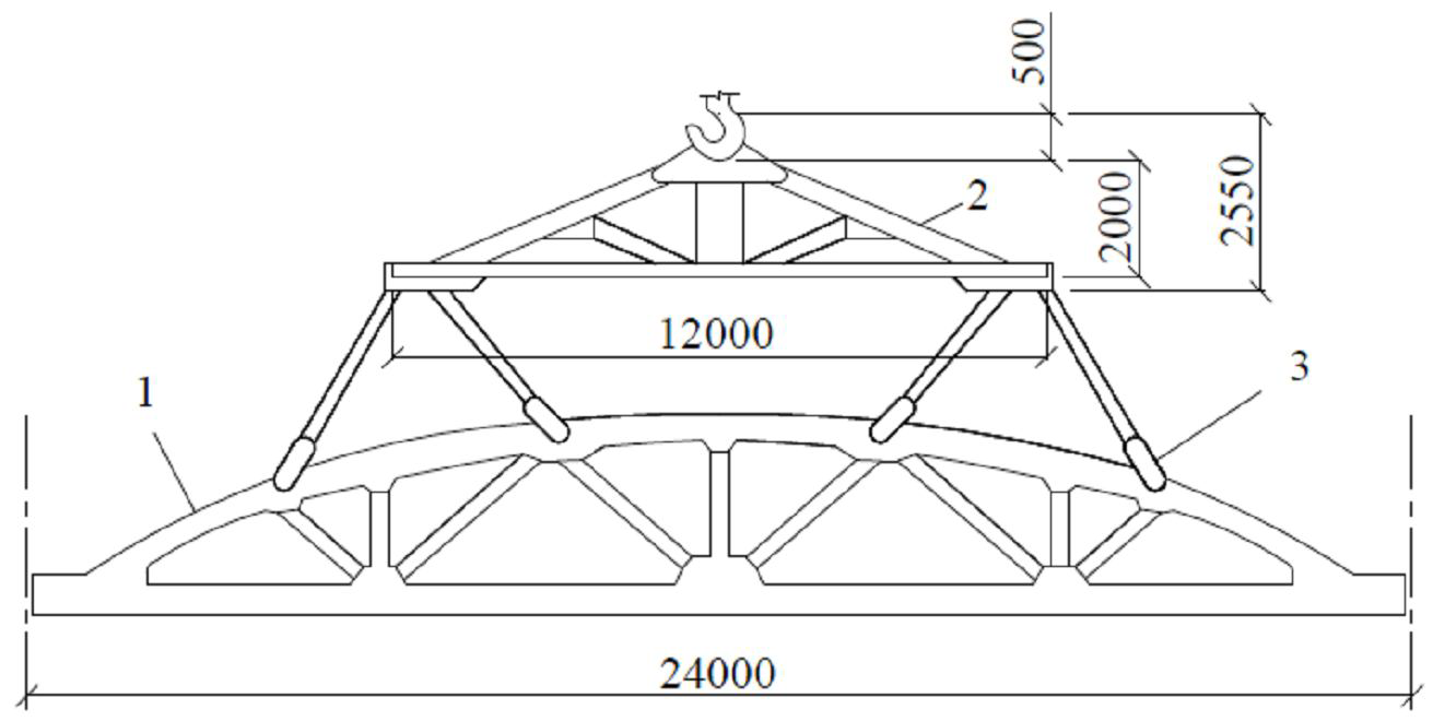
Slinging of reinforced concrete trusses: 1 - truss; 2 - traverse;
3 - semi-automatic metal gripper
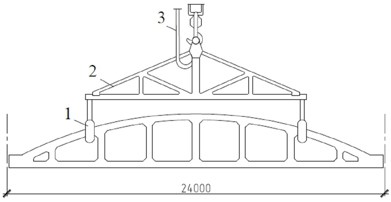
Semi-automatic gripper for mounting reinforced concrete trusses
1 - grippers; 2 - rigid traverse; 3 - cable
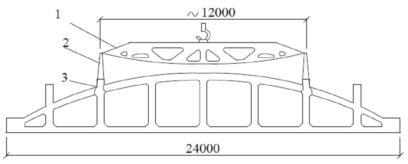
Universal traverse: 1 - traverse; 2 - sling VK-4/5000;
3 - automatic gripper
Fig. 5. Types of slinging devices for mounting trusses
Installation of prefabricated reinforced concrete roof girders
A beam is a structural element, usually in the form of a beam, working mainly in bending 12.
Beams are divided into types:
- by structural solution: two-slit, one-slit, with
supporting plates on the top;
- According to the way they are supported on the column: with undercut (on the hidden cantilever);
without trimming (on the column or on the open bracket).
When beams arrive at the construction site, it is necessary to
perform the following operations:
- checking the availability of the accompanying document on the quality of the products and their compliance with the specified type (grade) - GOST 18980-90, GOST 4893.0-81;
- checking for marking and quality control stamp according to GOST 13015-2003 and their compliance with the data specified in the accompanying document;
- preliminary visual inspection of items to determine
a preliminary visual inspection of the products to make sure there are no inadmissible defects and damages (cracks, concrete damages in the anchorage area of the tension armature, chipping, concrete overlapping) and whether the reinforcing bars are exposed to the
joints.
Usually, beam mounting is performed in one stream with floor and roof slabs using self-propelled jib cranes with crane booms or tower cranes and mounting accessories.
The deviations from the designed position of the assembled beams and girders must not exceed the limit deviations:
- from the alignment of landmarks (marks of geometric axes, faces) in the lower section of the installed elements with mounting landmarks - 8 mm;
- from the alignment of reference points (marks of geometric axes) in the upper section of the installed elements with reference points at the height of the element on the support, m
up to 1 - 6 mm;
from 1 to 1.6 - 8 mm;
- symmetricity (half of the difference in the depth of the element ends resting) in the direction of the span to be bridged, with the length of the element, m
up to 4 - 5 mm;
from 4 to 8 - 6 mm;
8 to 16 - 8 mm.
To lift the beams use the beams shown in Fig. 6.
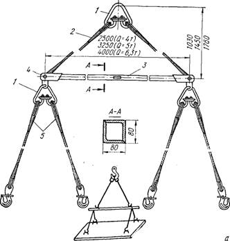
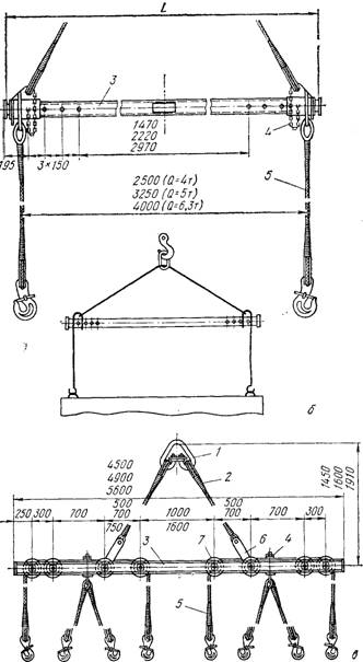
Fig. 6. Beam traverse: a - with
Two-branch slings; b - with pedestal
double-branch slings; b - cross-strings; c - universal; d - cross-strings
universal; 1 - suspension; 2 - sling rope; 3
- Beam; 4 - sling attachment; 5 - wire rope
Sling; 6 - shackle; 7 - roller.
Installation of precast reinforced concrete slabs
Slab - horizontal planar element of the structure designed to absorb vertical operating loads and transfer them to the load-bearing elements - beams, beams, columns, walls, etc.; used in the construction of buildings and structures for various purposes and perform a variety of functions (load-bearing, enclosing, sound-absorbing, etc.).
When the boards arrive at the construction site, the following operations should be performed:
- check the availability of the accompanying document on the quality of the boards and their compliance with the specified type (grade) - GOST 9561-91, GOST 21506-87,
GOST 27215-87;
- inspection of the availability of labeling on the boards (GOST 13015-2003) and their compliance with the data specified in the accompanying document;
- a preliminary visual inspection of the plates to detect inadmissible defects and damage (cracks, concrete damage in the area of stressed concrete anchorage, chipping, concrete overlap).
Assessment of installation quality of all the installed plates is performed using modern geodesic tools and other measuring equipment which allow to detect the plate position deviations from the design parameters with an error not exceeding 0.2 of the value of the limit (admissible) deviation. Selection of measuring instruments is performed in accordance with GOST 23616-79 and GOST 26433.1-89.
Depending on the sequence of installation of the elements of an industrial building mounted separate, integrated or combined method [1 - 4].
In the separate method a crane for each passage establishes the design of one type (for the first - the columns, the second - trusses, the third - floor slabs).
The complex method provides for the successive installation of structures of different types within one or several adjacent building cells forming a rigid stable system.
The combined method is a combination of the separate
and the complex method. For example, columns and trusses
are installed separately, while the trusses and floor slabs are installed in a combined manner.
Список литературы
- ТЕХНОЛОГИЯ СТРОИТЕЛЬНОГО ПРОИЗВОДСТВА; Хамзин С. К., | Карасев А. К.
- ТЕХНОЛОГИИ И ОРГАНИЗАЦИЯ СТРОИТЕЛЬСТВА; Федулов Е.С., Иванов Я.В.
- Industrial building Planning and Design; Julian Weyer
- Design of Industrial Steel Buildings Using Staad Pro: With Indian Examples; T .S. Sarma
- Соколов Г.К. Технология строительного производства: учебное пособие для студентов ВУЗов. – М.: Академия, 2006. – 544 с.
- Хамзин С.К., Карасев А.К. Технология строительного производства. Курсовое и дипломное проектирование. – М.: Высшая школа, 2004. – 216 с.
- Монтаж стальных и железобетонных конструкций. Справочник монтажника / Под ред. Олесова И.П. – М.: Стройиздат, 1980. – 863 с.


